Proteus Digital Health, Inc.
Michael Sheehan | 07/08/2020 | Bankruptcy
Patent Backed Bankruptcy Report
Company Background:
Proteus Digital Health, Inc. operates as a digital medicines company. The company focuses on developing products, services, and data systems based on integrating medicines with ingestible, wearable, mobile, and cloud computing. Its digital health feedback technology provides a view into an individual’s personal health choices and physiologic response, allowing patients to manage their health, and collaborate with caregivers and clinicians. Proteus Digital Health, Inc. was formerly known as Proteus Biomedical, Inc. and changed its name to Proteus Digital Health, Inc. in July 2012. Proteus Digital Health, Inc. was founded in 2001 and is headquartered in Redwood City, California. On June 15, 2020, Proteus Digital Health, Inc. filed a voluntary petition for reorganization under Chapter 11 in the U.S. Bankruptcy Court for the District of Delaware.
Address
Ownership
Industry
2600 Bridge Pkwy Suite 101
Redwood City, CA 94065
Private
Biotechnology
| Chapter Type | Case Number | Assets | Liabilities | Industry/Description |
| 11 | 20-11580-BLS | $100,000,000-$500,000,000 | $10,000,000-$50,000,000 | Biotech and Pharmaceuticals |
| Portfolio Valuation Range | Asset Valuation Range | Total Assets Valuation Range | Liability Range | Leverage Ratio Range |
| $1,975,000.00 – $7,900,000.00 | $50,000,000.00 – $500,000,000.00 | $51,975,000.00 – $507,900,000.00 | $5,000,000.00 – $37,500,000.00 | 1.386 – 101.58 |
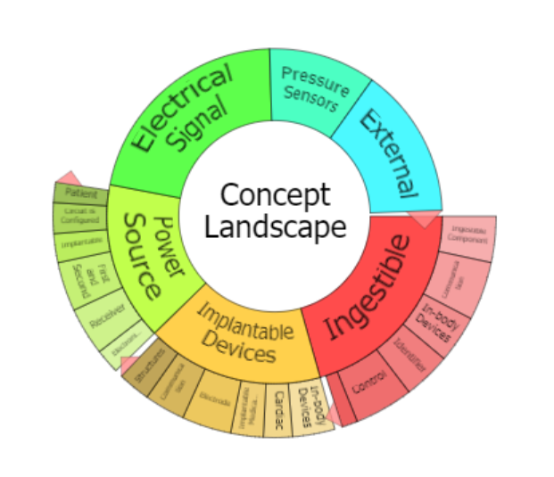
Patent Portfolio Breakdown
102 Total Assets
- 79 Active US Patents
- 23 Foreign Counterparts
Featured Assets
Abstract:
A re-wearable wireless device includes a reusable component to be secured to a disposable component. The reusable component includes a sensor interface to receive signals from an electrode secured to a living subject and monitors physiological and physical parameters associated with the living subject and a cellular wireless communication circuit. An adhesive base the device includes a first adhesive layer and a second adhesive layer partially covering the first adhesive layer around a perimeter thereof, where the first and second adhesive layers include different adhesives. A method of establishing a link between two wireless devices is also disclosed, where a first wireless device with an insignia representing a communication channel address identification is provided. An image of the insignia is captured with a mobile telephone computing device comprising an image sensor. The captured image is processed to extract the communication channel address identification represented by the insignia.
Claim 1:
1. A device comprising:
a disposable component comprising:
a mechanical snap-in connect mechanism comprising:
a base portion comprising a first electrical contact and a second electrical contact; and
a pair of projecting elements that are connected to the base portion and extend from the base portion, wherein the pair of projecting elements extend along opposite edges of the base portion and are substantially parallel to each other, and the first and second electrical contacts are arranged between the projecting elements and along a line substantially parallel to the projecting elements; and
a first electrode electrically coupled to the first electrical contact and a second electrode electrically coupled to the second electrical contact, wherein the first electrode and the second electrode are configured to be secured to a living subject; and
a reusable component configured to operably engage the projecting elements and configured to be secured to the disposable component when the reusable component is engaged with the projecting elements and at least a portion of the reusable component is located between the projecting elements, the reusable component comprising:
a sensor interface configured to receive signals from the first and the second electrodes configured to be secured to the living subject and monitor one or more physiological and physical parameters associated with the living subject, wherein the sensor interface comprises a third electrical contact and a fourth electrical contact on a surface of the reusable component, wherein the third and fourth electrical contacts are arranged such that when the reusable component is attached to the disposable component, the third electrical contact is coupled to the first electrical contact, and the fourth electrical contact is coupled to the second electrical contact;
a cellular wireless communication circuit; and
a transbody conductive communication module configured to communicate with an event maker system in a body of the living subject.
Abstract:
Implantable pressure sensors and methods for making and using the same are provided. A feature of embodiments of the subject pressure sensors is that they are low-drift sensors. The subject sensors find use in a variety of applications.
Claim 1:
1. A method for measuring cardiac pressure, the method comprising:
configuring a pressure sensor for measuring cardiac pressure; and
Abstract
The invention provides a receiver associated with a body, e.g., located inside or within close proximity to a body, configured to receive and decode a signal from an in vivo transmitter which located inside the body. Signal receivers of the invention provide for accurate signal decoding of a low-level signal, even in the presence of significant noise, using a small-scale chip, e.g., where the chip consumes very low power. Also provided are systems that include the receivers, as well as methods of using the same.
Claim 1:
1. A signal receiver comprising:
.

Michael is interested in how companies value their IP. These reports are focused primarily on the value IP brings to Companies after filing for bankruptcy.